Backyard Model Ski Chairlift Personal Project | Spring 2026 - Present
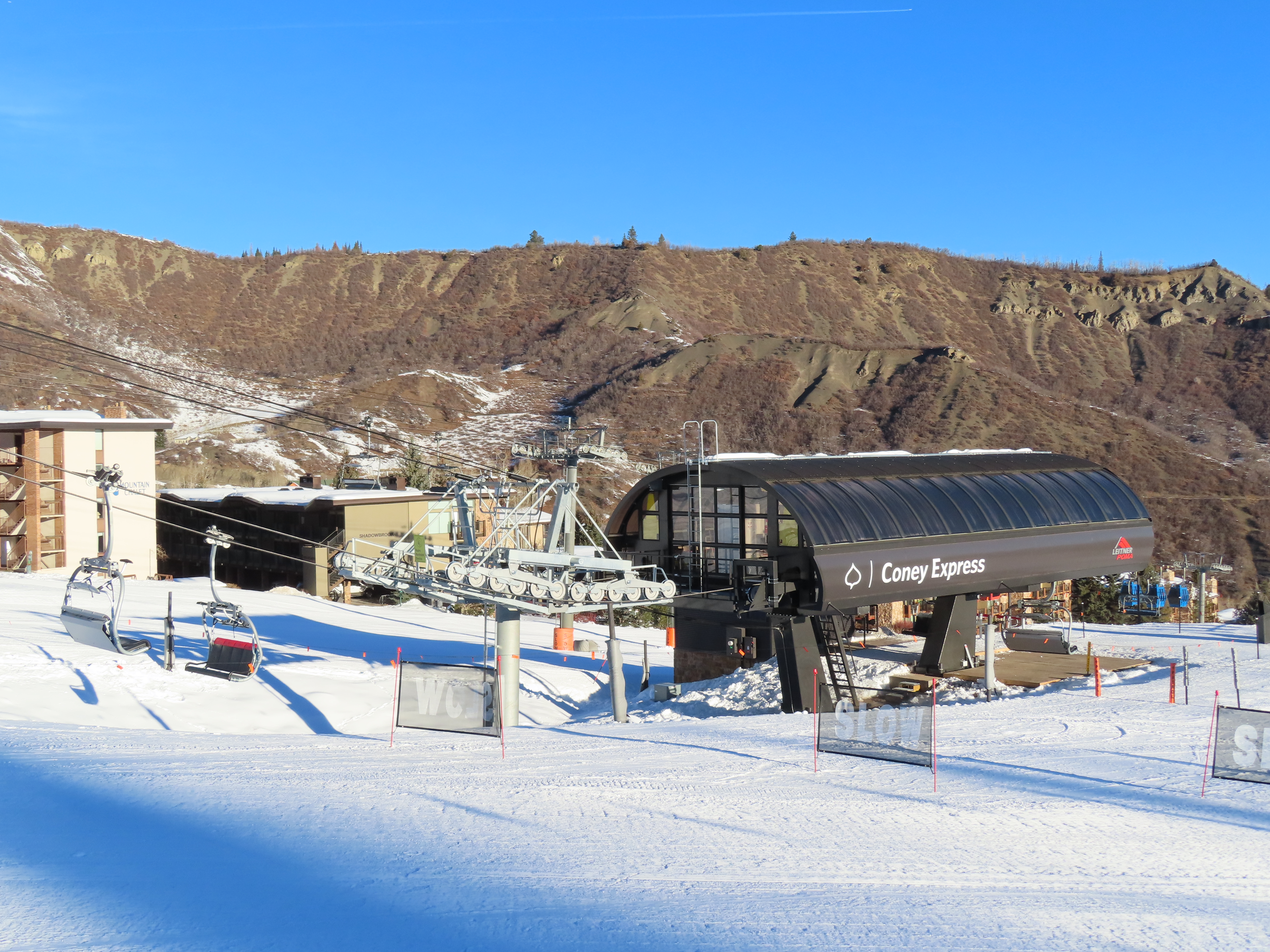
The goal of this personal project is to create a model ski chairlift that can run in a backyard. The idea arose when visiting my aunt and uncle in Colorado. They live in the mountains, and my uncle really loves to ski and snowboard. He also has a backyard located on the side of a hill that he has spent time landscaping. When I most recently visited, he mentioned the idea of having a scale model ski chairlift or gondola in his backyard and showed me some reference videos. These types of model ski lifts are available to be purchased, but I had the idea that I might be able to turn it into a fun project for myself. Plus, there are a few benefits to having something of this sort designed and custom built as a one-off by a relative.
This project page will likely be formatted differently than several others on my website, as I have written the project descriptions for the others long after completing them. However, I am revamping my projects page at the same time as I develop this project. Because of this, developments in this project will be documented in a chronological manner with updates being dated and written as the project progresses.
As I’m currently acting as the systems engineer for my senior design project team, I feel that it’s only fitting that I frame this project using requirements. Initially, my self-imposed requirements include the following:
- R1: The system shall be weather resistant and operable from April to October in Aspen, Colorado.
- R2: The system shall be able to be turned on and off with a physical switch
- R3: The system shall be compatible with Apple HomeKit
- R4: The system shall be able to traverse a minimum of 8 vertical feet and 16 horizontal feet
Most components will be 3D printed using a Bambu Lab P1S printer and AMS system. All CAD will be done in Autodesk Fusion, as I currently have an educational license and it runs on my Macbook.
1/24/26
- Initial Chair Design and Prototype
- Intiail Gondola Design and Prototype
- Testing ESP32 Microcontroller
The first item on my list was to design the chairs and gondolas. I decided to design them both because my uncle had initially talked about a model gondola, but I realized that a chair would be easier to design and lighter at the same scale. Therefore, I worked on both.
I started with a 4-seater chair design about 4 inches wide. The components consisted of a seat bottom, seat back, 2 side brackets, and a top bar. While the proportions of this design turned out well, I decided to move towards a 2-seater design at the same scale so that test prints used less material and took less time. I also added my first iteration of cable grip that connects the top bar to the cable. With this component it was essential that the arm come from one side at the cable so that it wouldn’t interfere with future tower wheels or the base station.
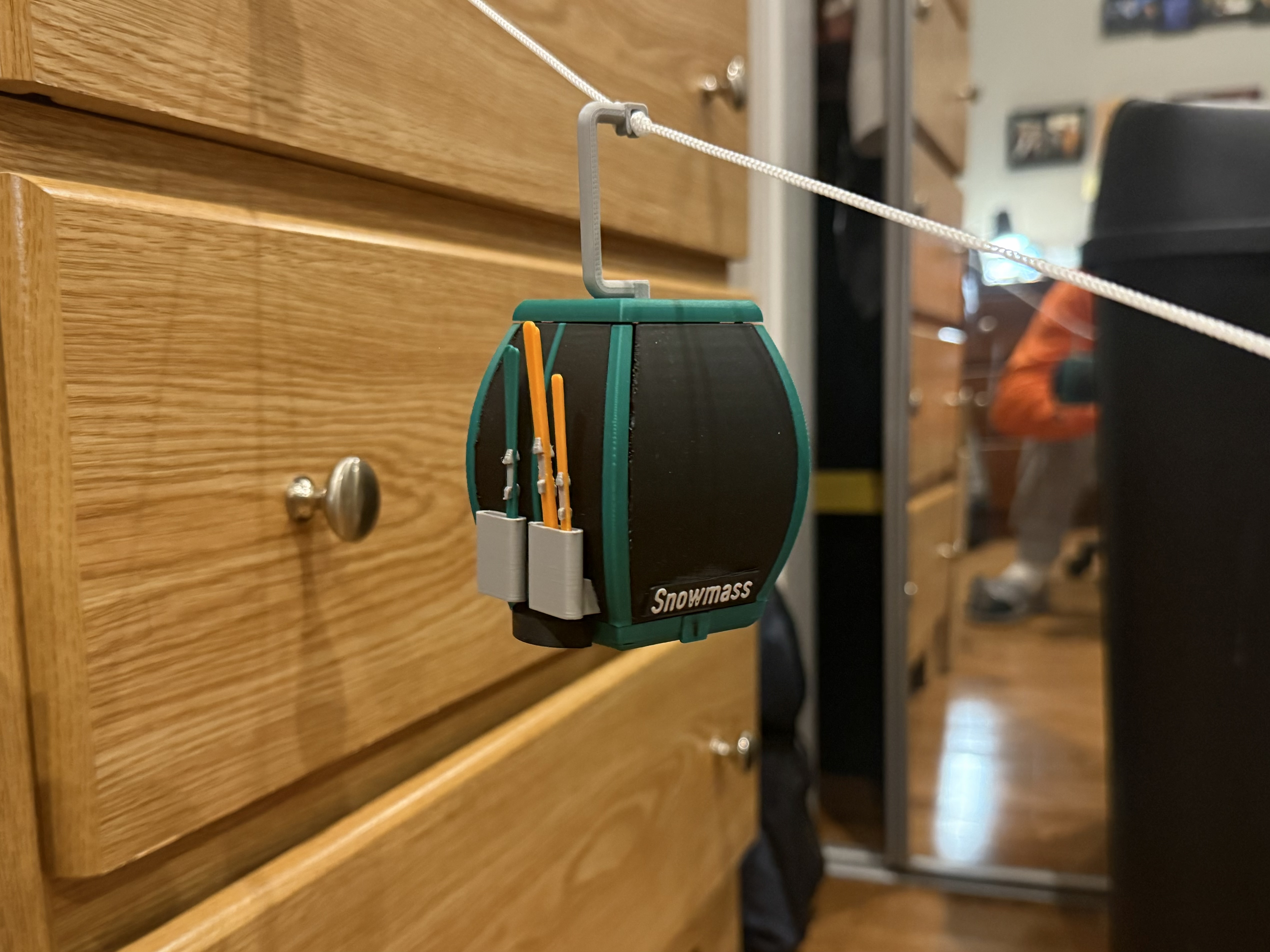
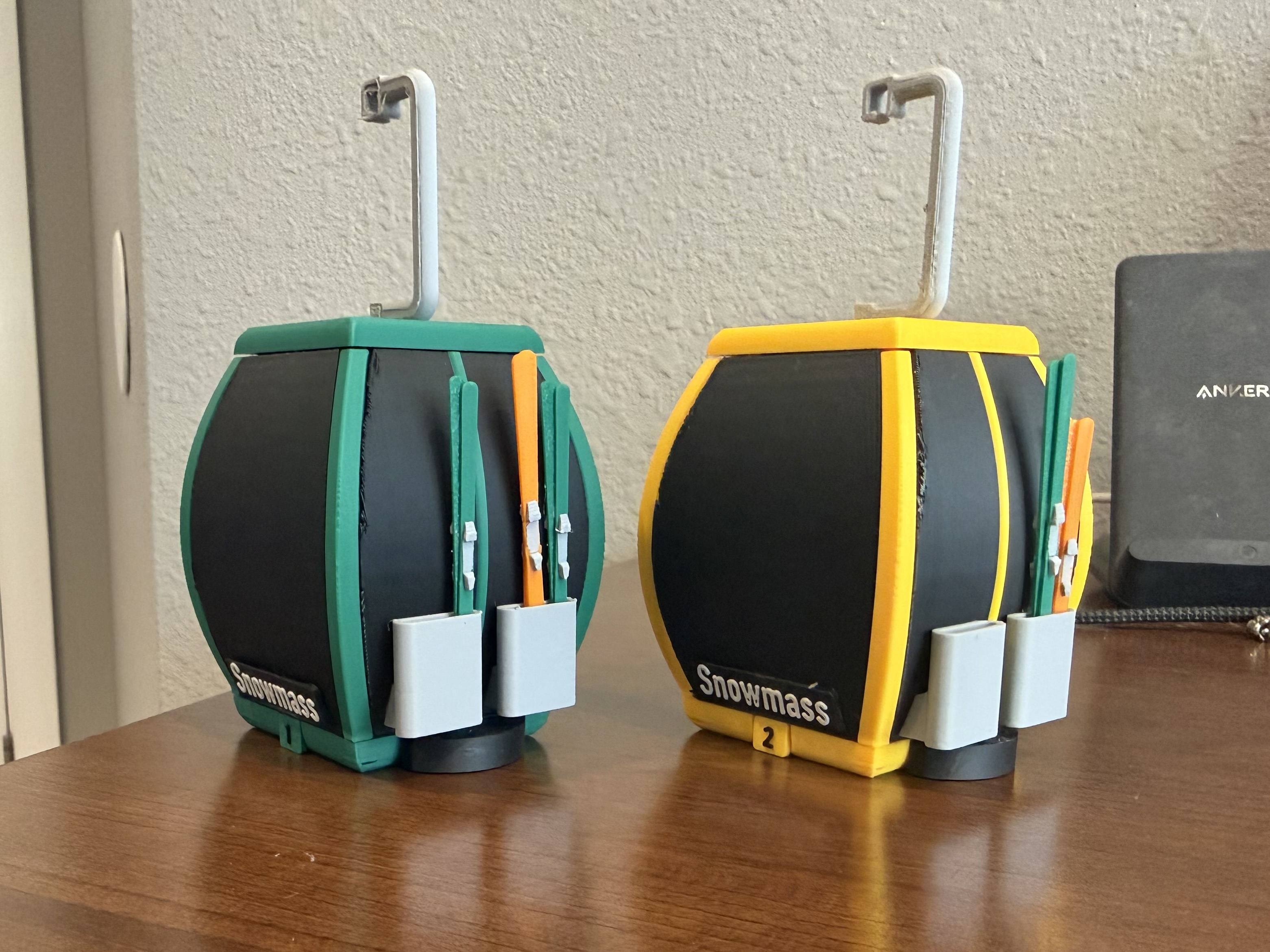
After feeling good about my chairlift design, I turned towards modeling a gondola. This design was a lot more complex and subsequently took much more time to design, prototype and finalize. The general scheme consists of a base section, a roof, 4 “windows”, and 4 corner posts. The windows and corner posts have slots on both top in bottom that fit into the base and roof. The corner posts and windows were designed as separate pieces to allow for multiple colors while not vastly increasing printing time. The base also has drain built in to allow any rainwater that might get inside of the model to naturally flow out (keeping requirement 1 in mind).
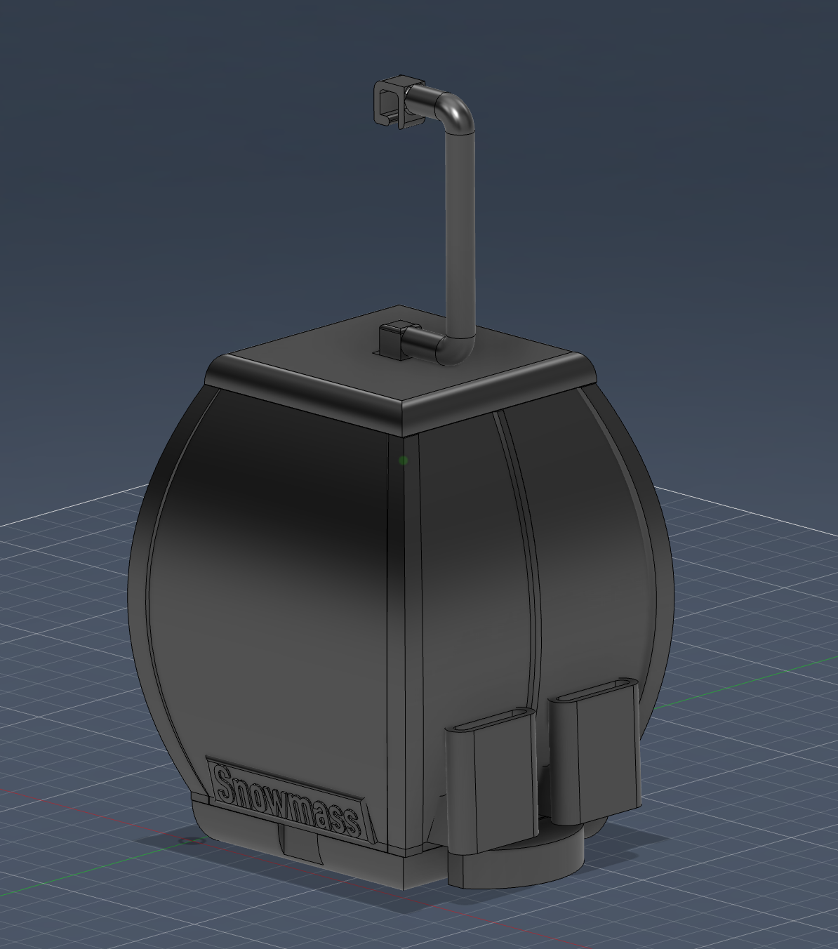
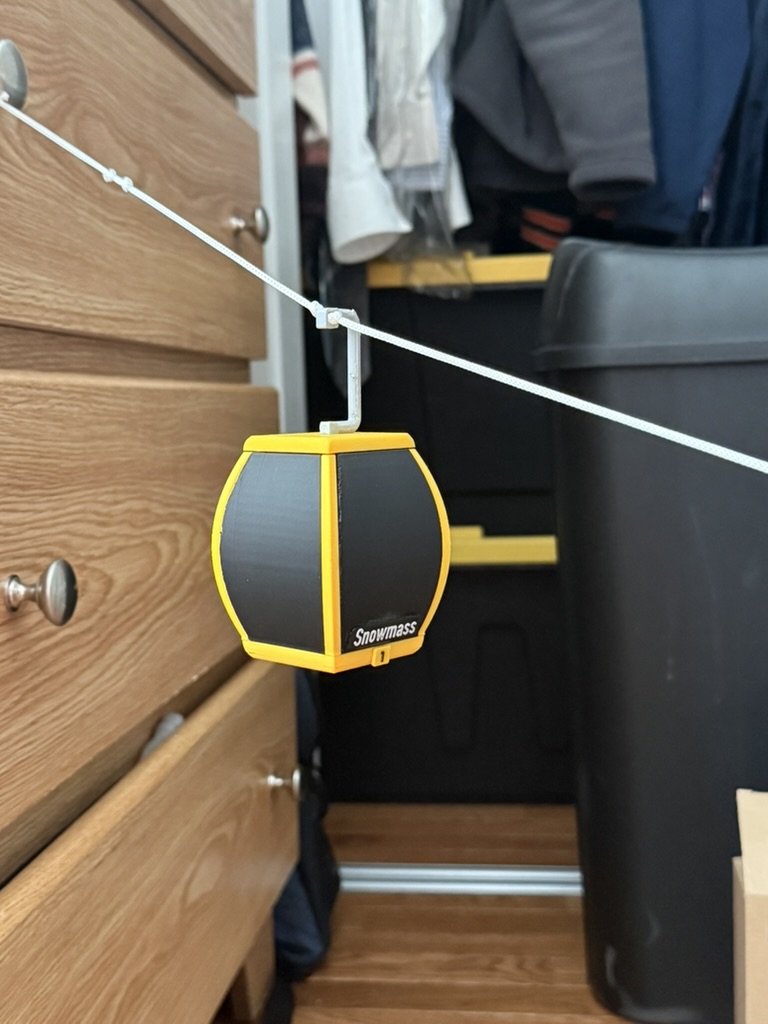
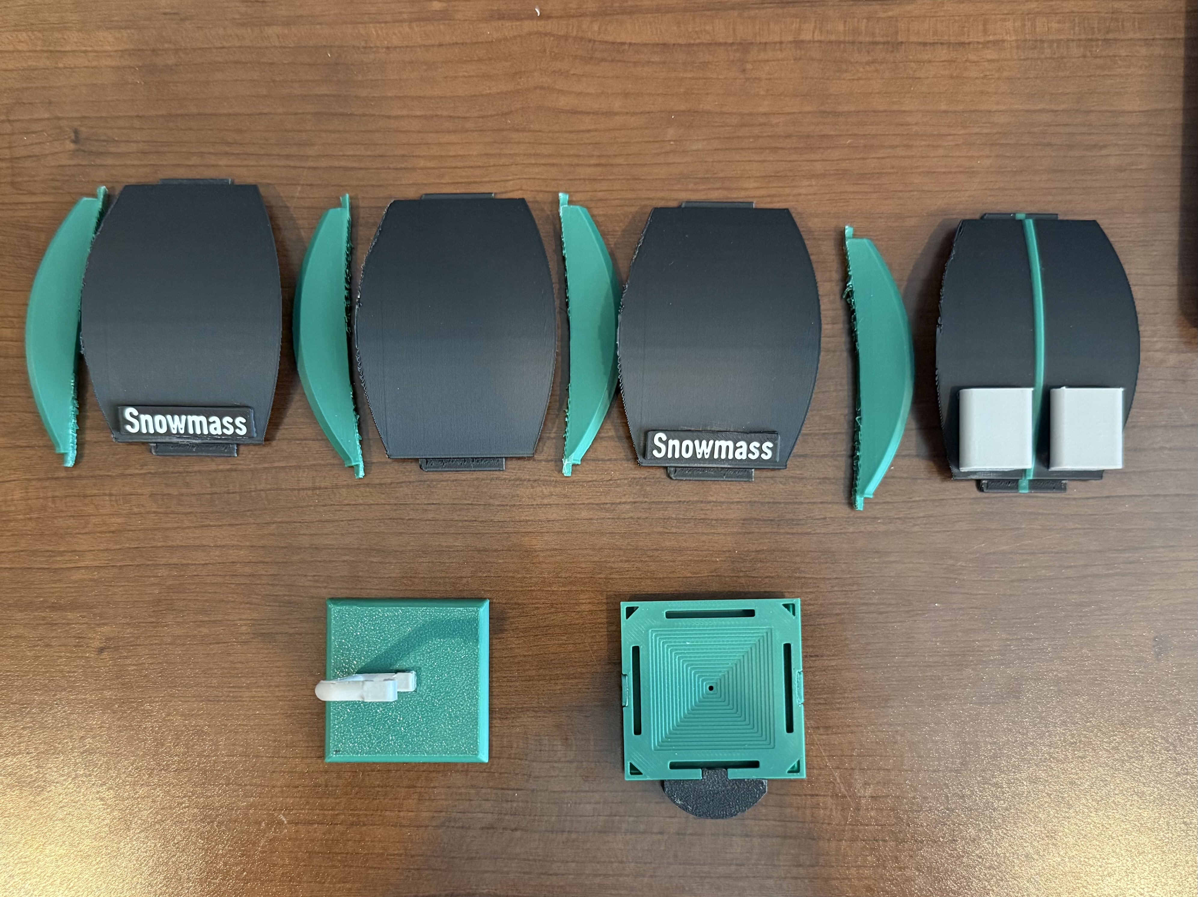
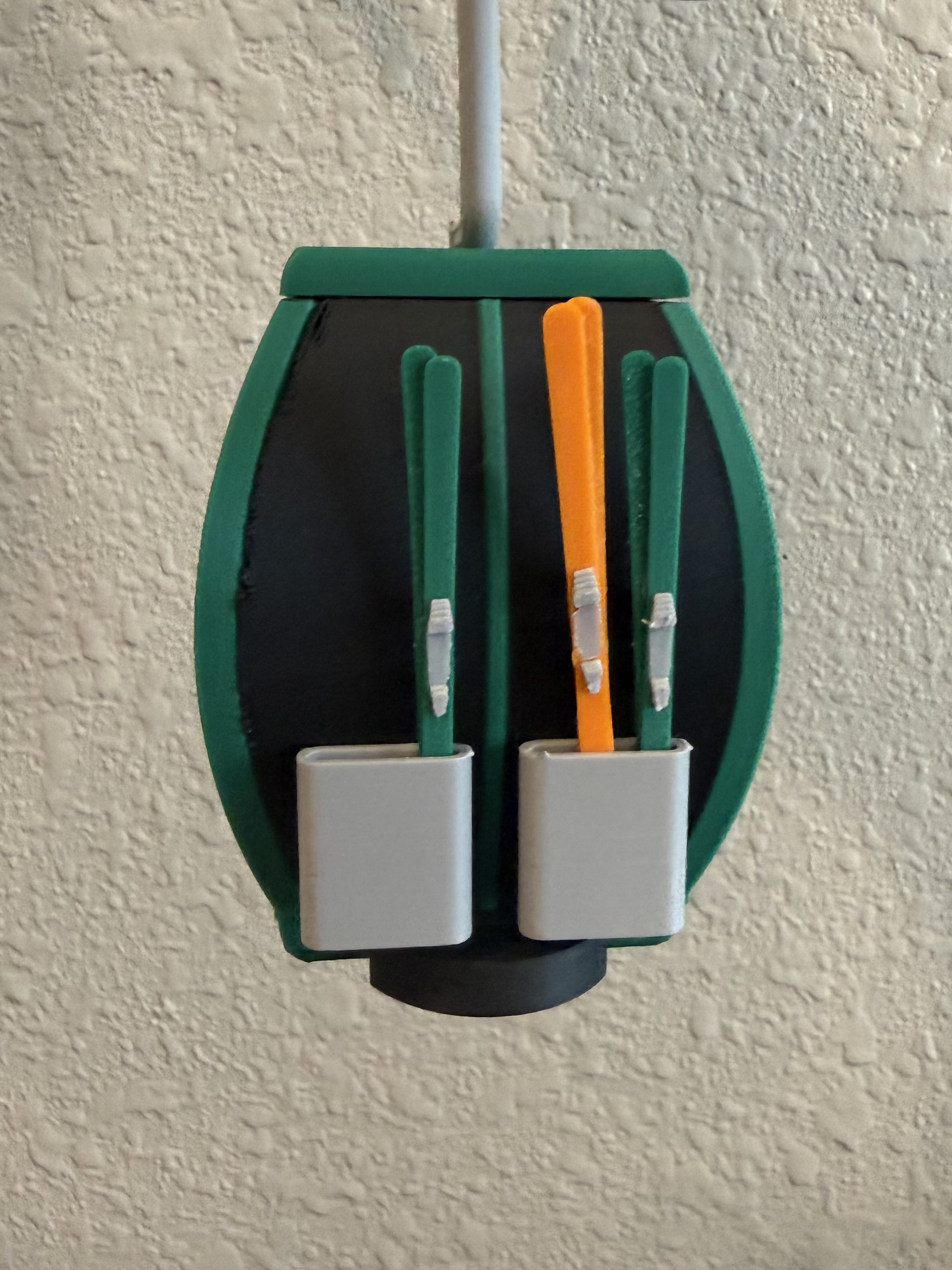
After finalizing the base design, I turned my attention to adding a few more details to improve upon the realism. First, I redesigned the window that would actually be a door on a real gondola so that it had an additional structural colored line in the center. Next, I designed ski and snowboard holders that are glued to the outer wall of the door. I also added a step that slots into the base underneath the door. Finally, I modified the base to have flat sections on each side where gondola numbers could be added. I also took a little time to model basic skis that could be placed in the ski racks.
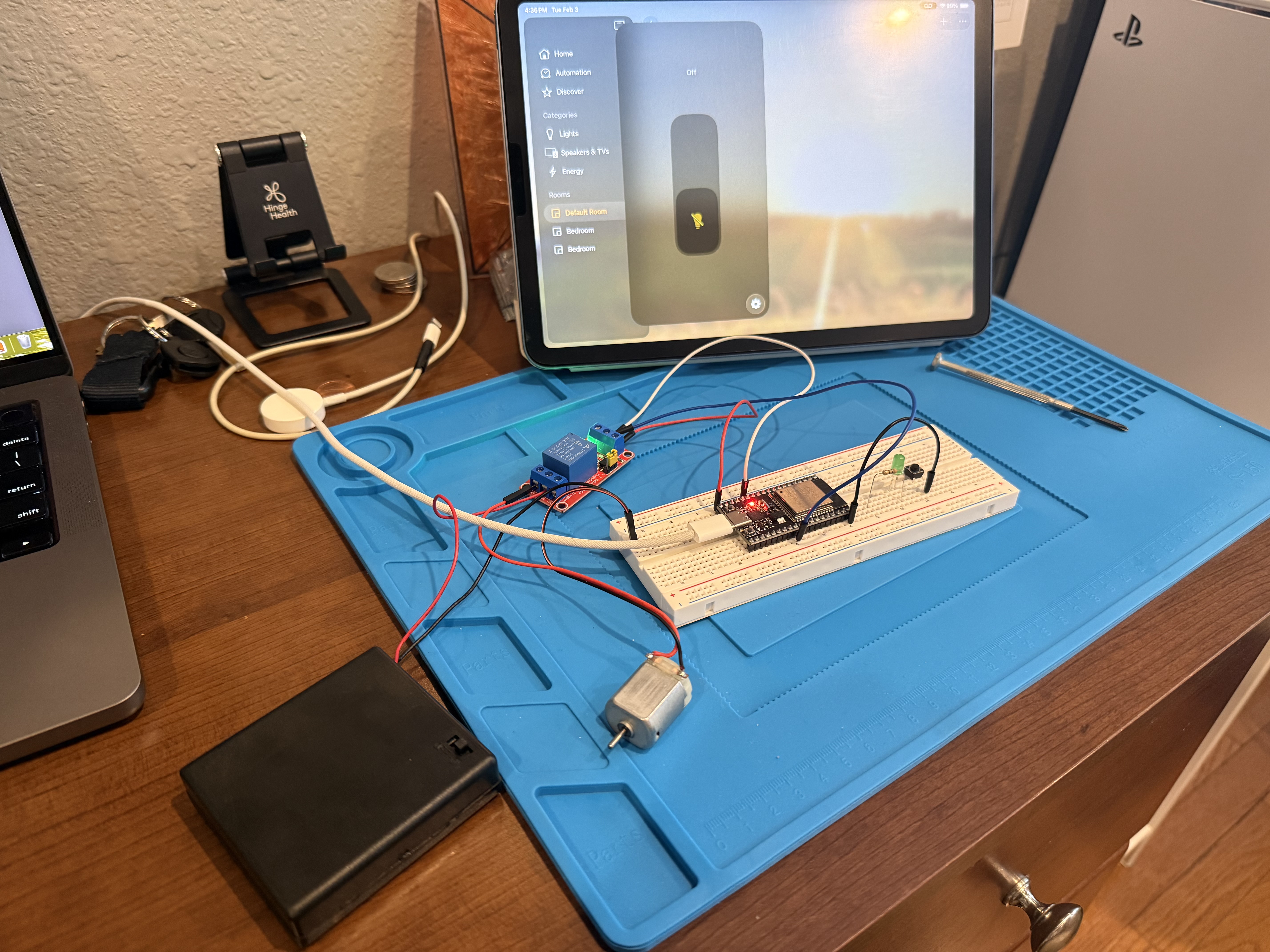
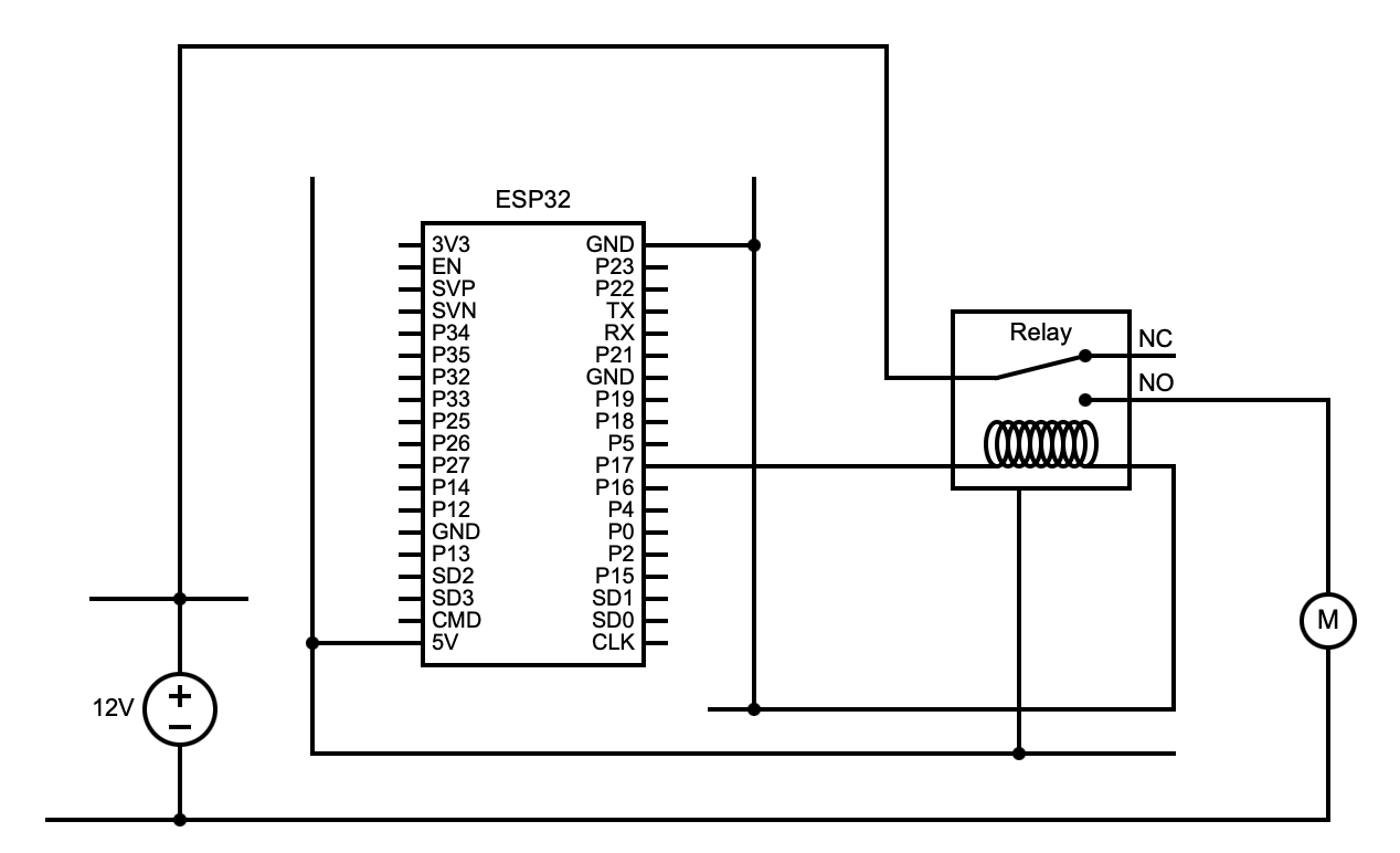
Finally, I ordered and received several ESP32 microcontrollers. I ordered this particular microcontroller because it is able to interface with Apple HomeKit through WIFI to allow for smart home control of any outputs. I did a little background research and ended up using the Arduino library “HomeSpan” to make the programming a bit easier. I then created a basic HomeKit script that allowed for toggling a light using the ESP32 and tested it with an LED. In the future this will be used to toggle a mechanical relay that powers on and off the motor in the lift’s base station.
1/31/26
- Initial Turn Wheel Design and Prototype
- Intial Motor and Bearing Adapter Designs and Prototypes
- Motor Post Design and Prototype
- Turn Wheel Test with Chair
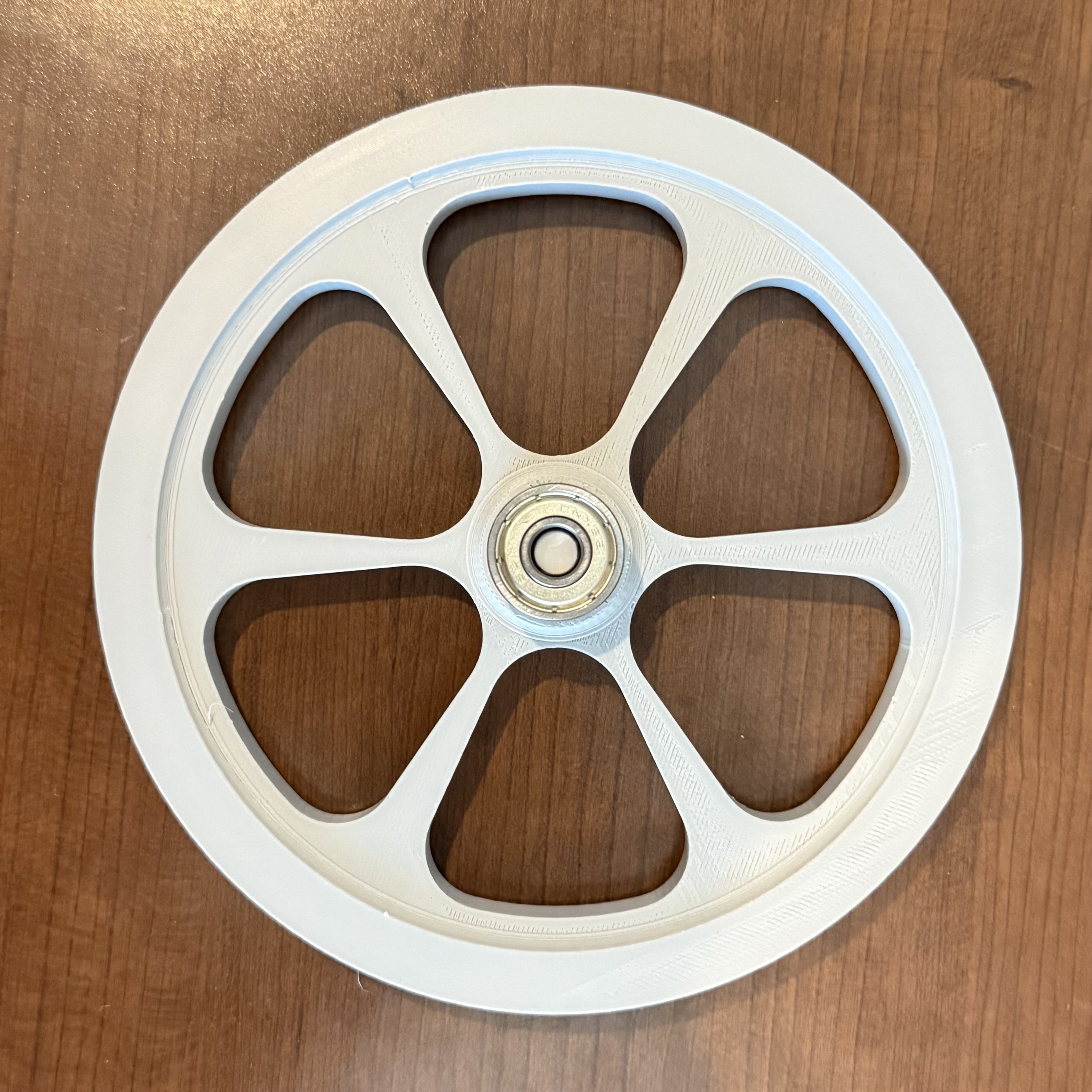
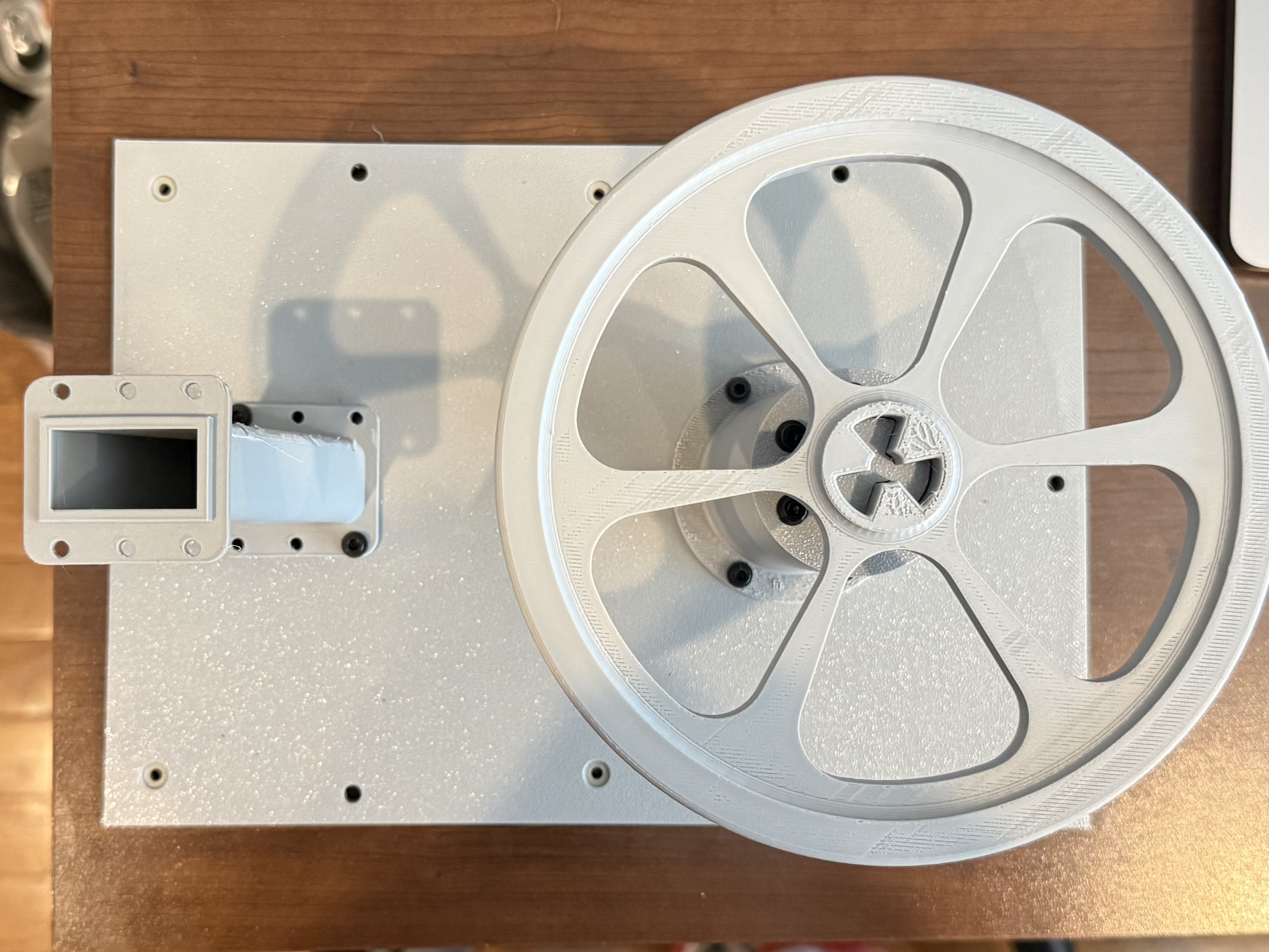
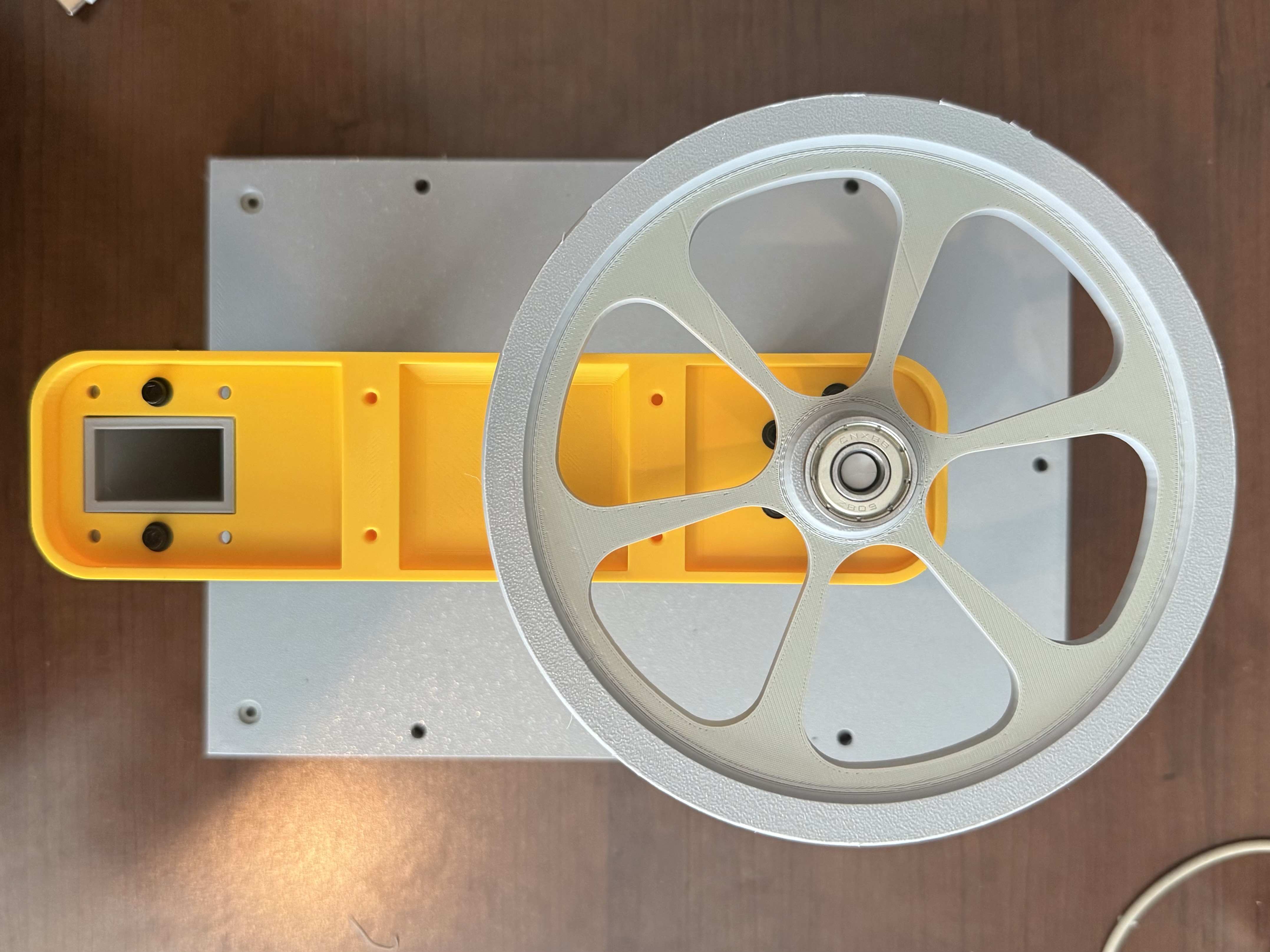
This week I turned my attention to the base station’s turn wheel. Which will be the primary mechanism for enabling movement of chairs. This first iteration has a channel on the outside that the lift cable can slot into, as well as a custom three-pronged interface in the center. This interface allows me to modify adapters for motors and bearings without reprinting the entire wheel.
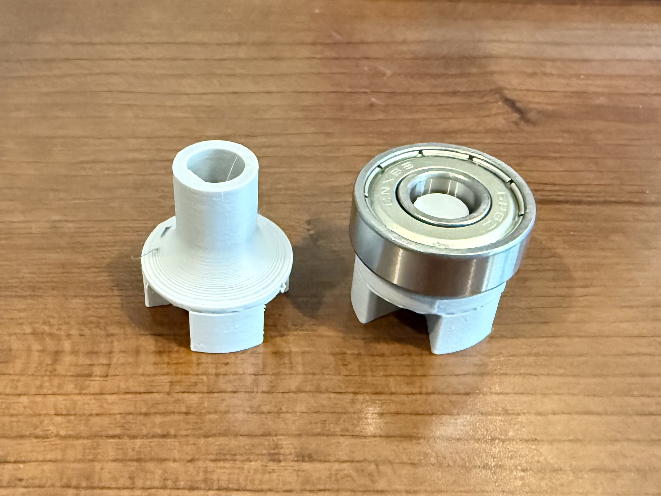
On that note, I also designed the motor and bearing adapters this week. I started with the motor adapter, printing 3 different tolerances until I found one that fit my motor shaft the best. I then turned my attention to the bearing adapter. This adapter will be used on both sides of the turn wheel at the top station, and on the top side of the turn wheel on the bottom station. The design uses a friction fit on the interior of the bearing by applying a narrowing chamfer to the cylinder on top. It took a couple of prototypes to find the right fit for this.
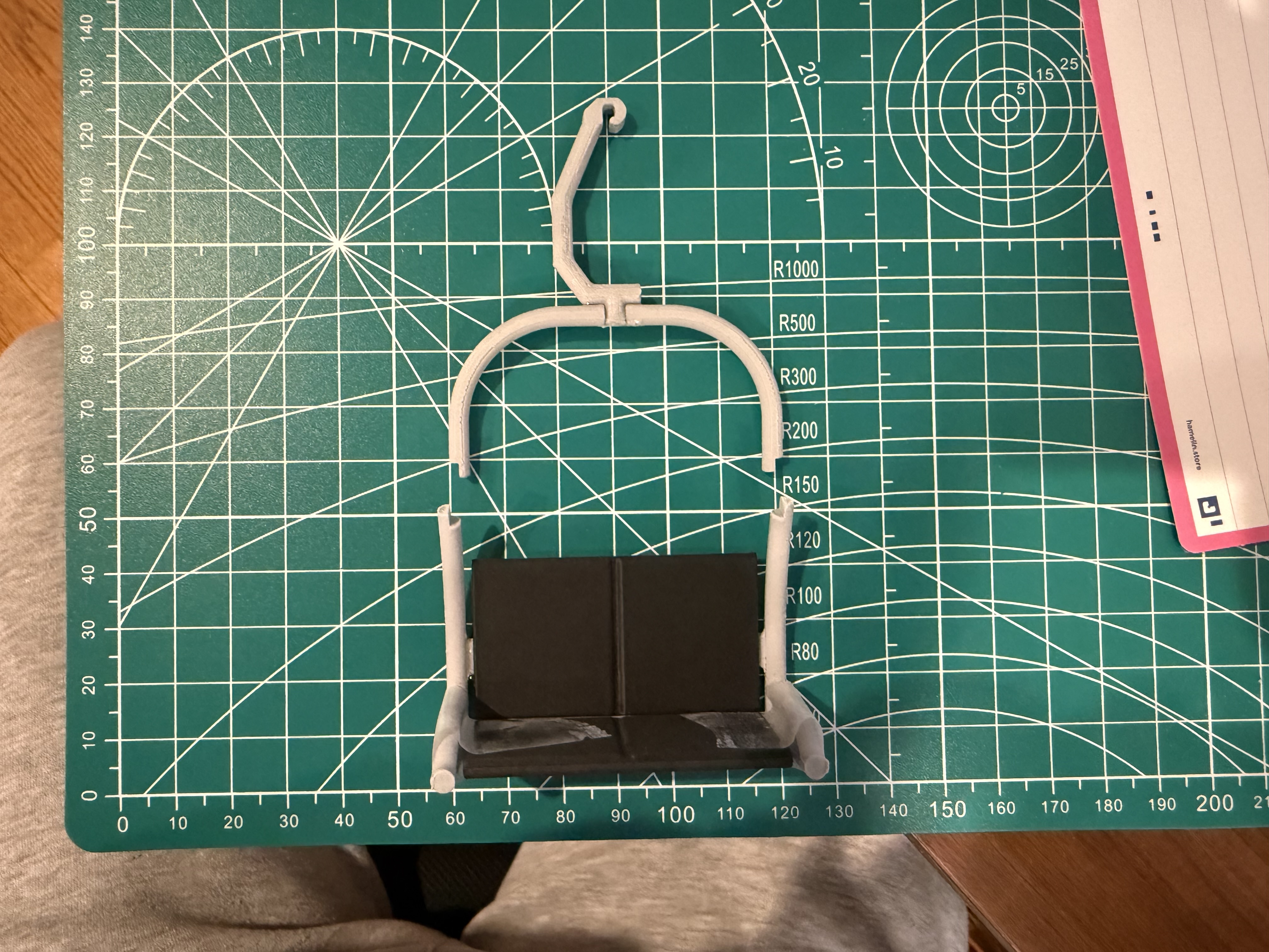
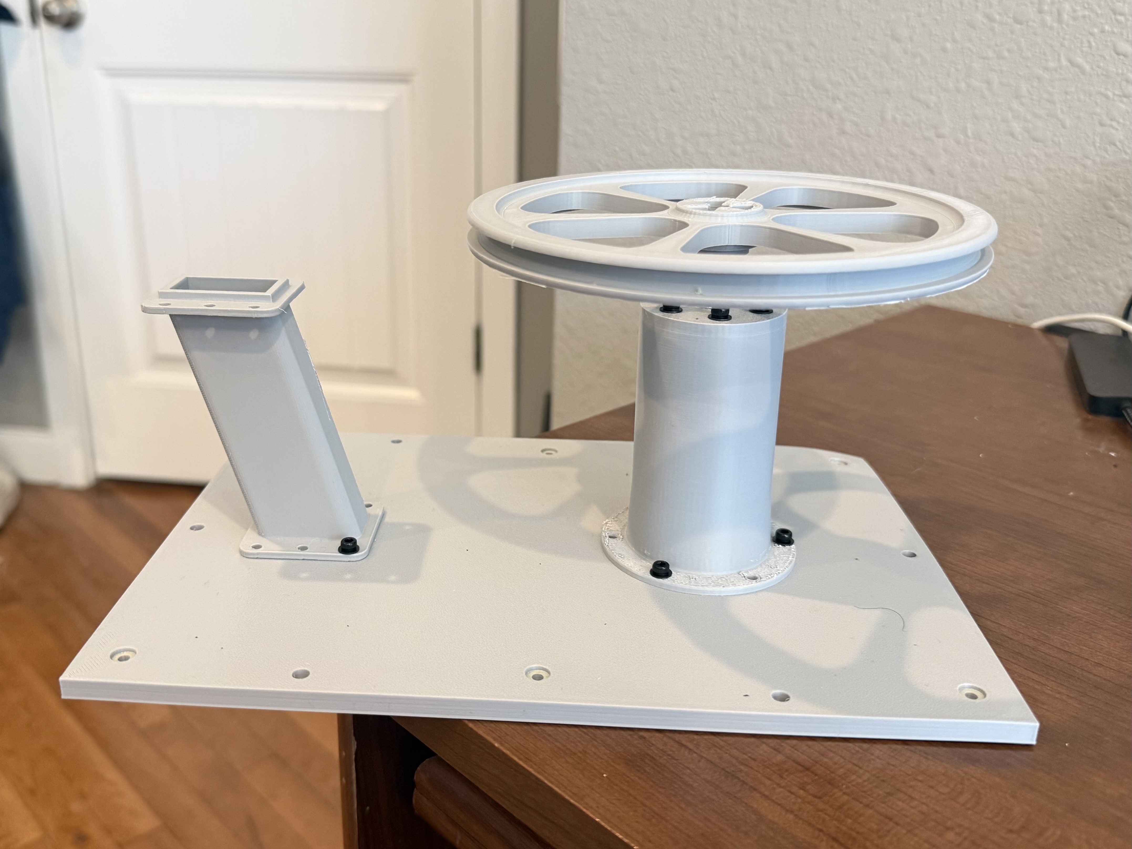
My last bit of design work for this week involved creating a motor post that would eventually mount the motor to the base station and hide any wiring. This ended up being a simple hollow cylinder with proper holes added on top and bottom for M3 screws. After getting the rough design down, I did a very rough test of the turn wheels and motor assembly with a test chair attached which you can see above.
2/7/26
- Updated Turn Wheel
- Base Station CAD and Prototype
After last week’s turn wheel test, I realized that the channel was two shallow and too tall. Therefore, I made a slight redesign to the wheel that gave more of a ledge for the cable to rest on. I also modified the center slightly to allow for wheel adapter placement on both the top and bottom.

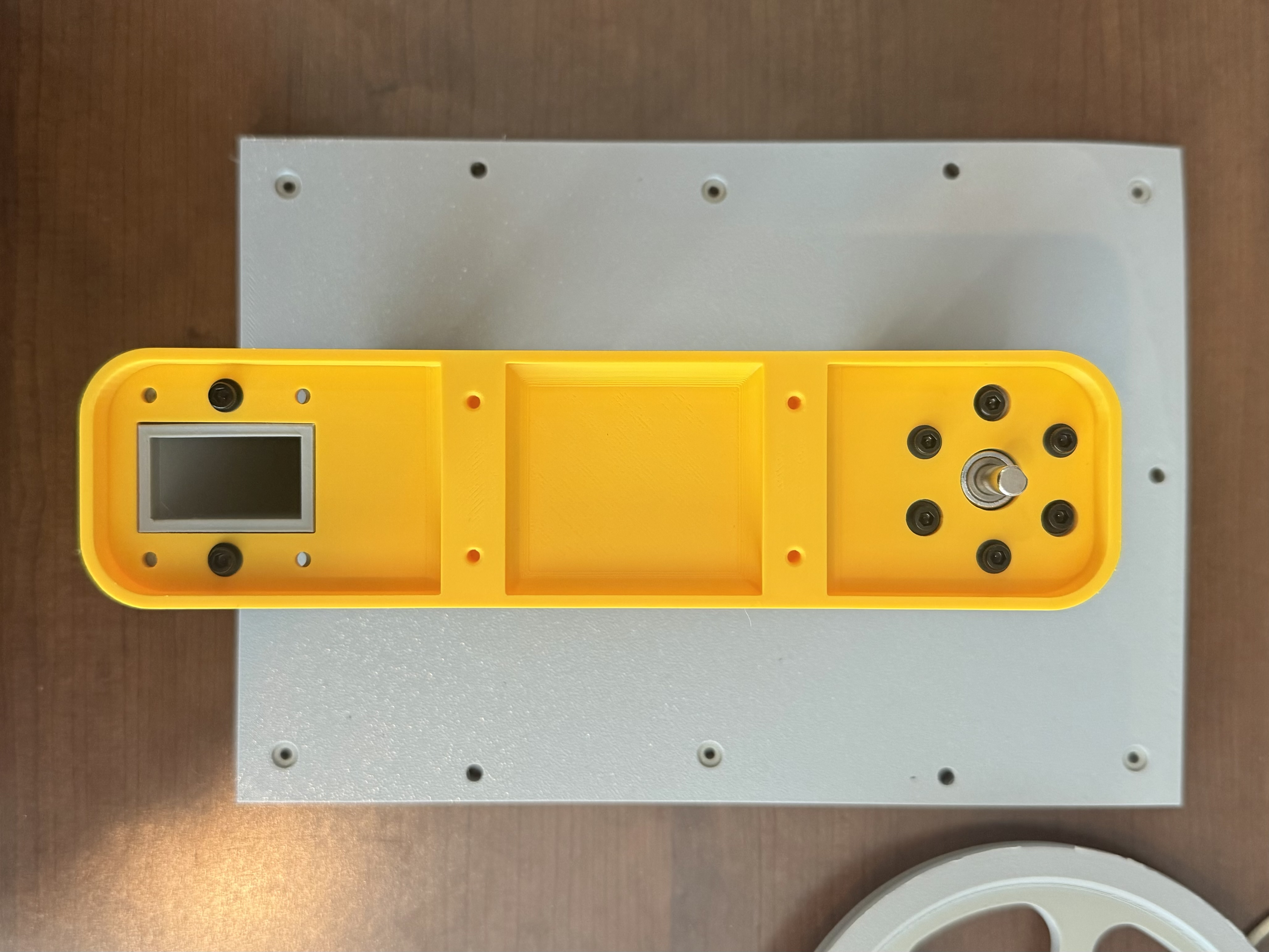
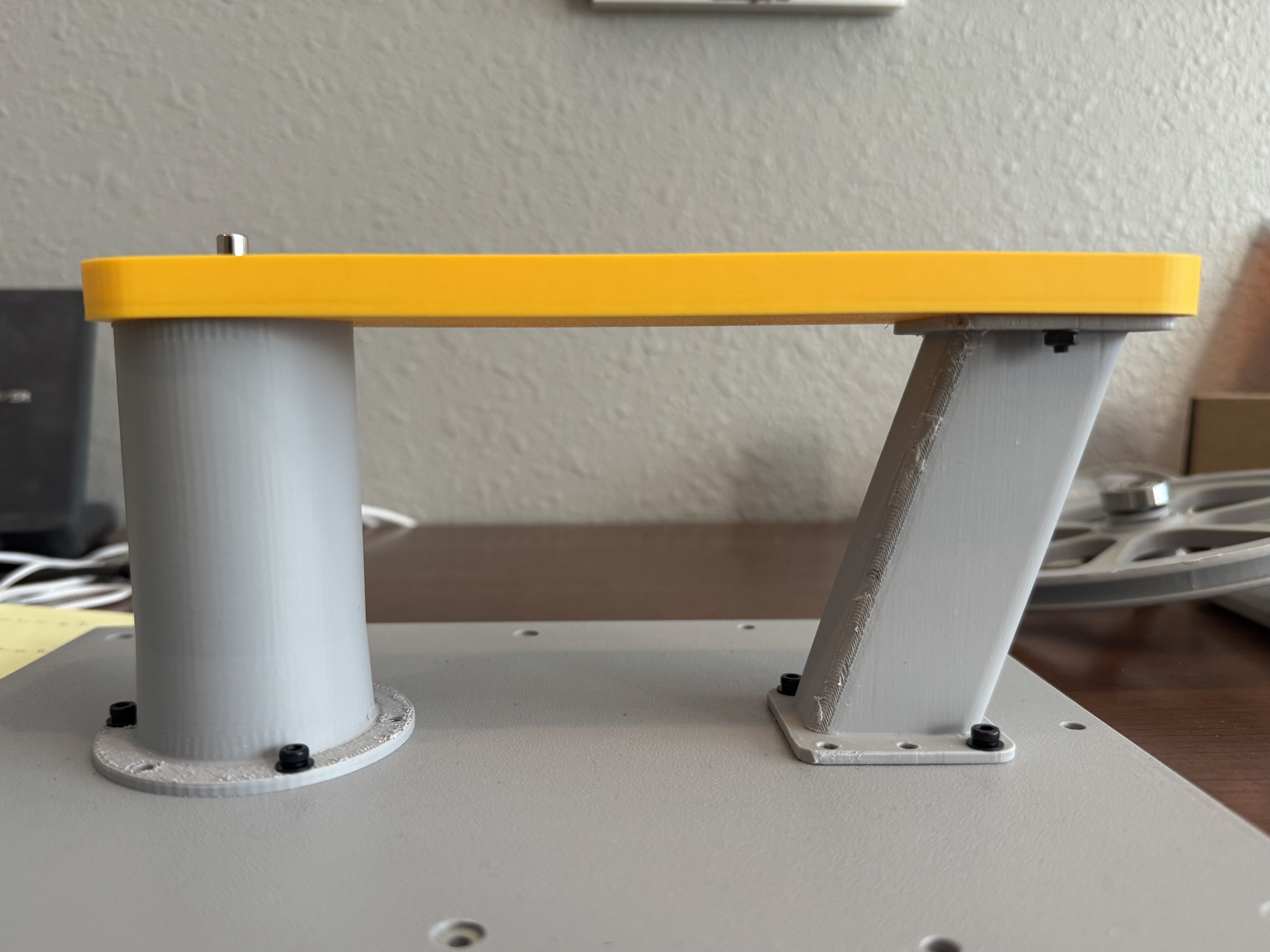
I also continued with my base station CAD modeling. I designed a baseplate for the mechanical elements to mount to, and for the motor wiring to be routed through. I also modeled and printed a secondary post to support the roof in addition to the motor post.
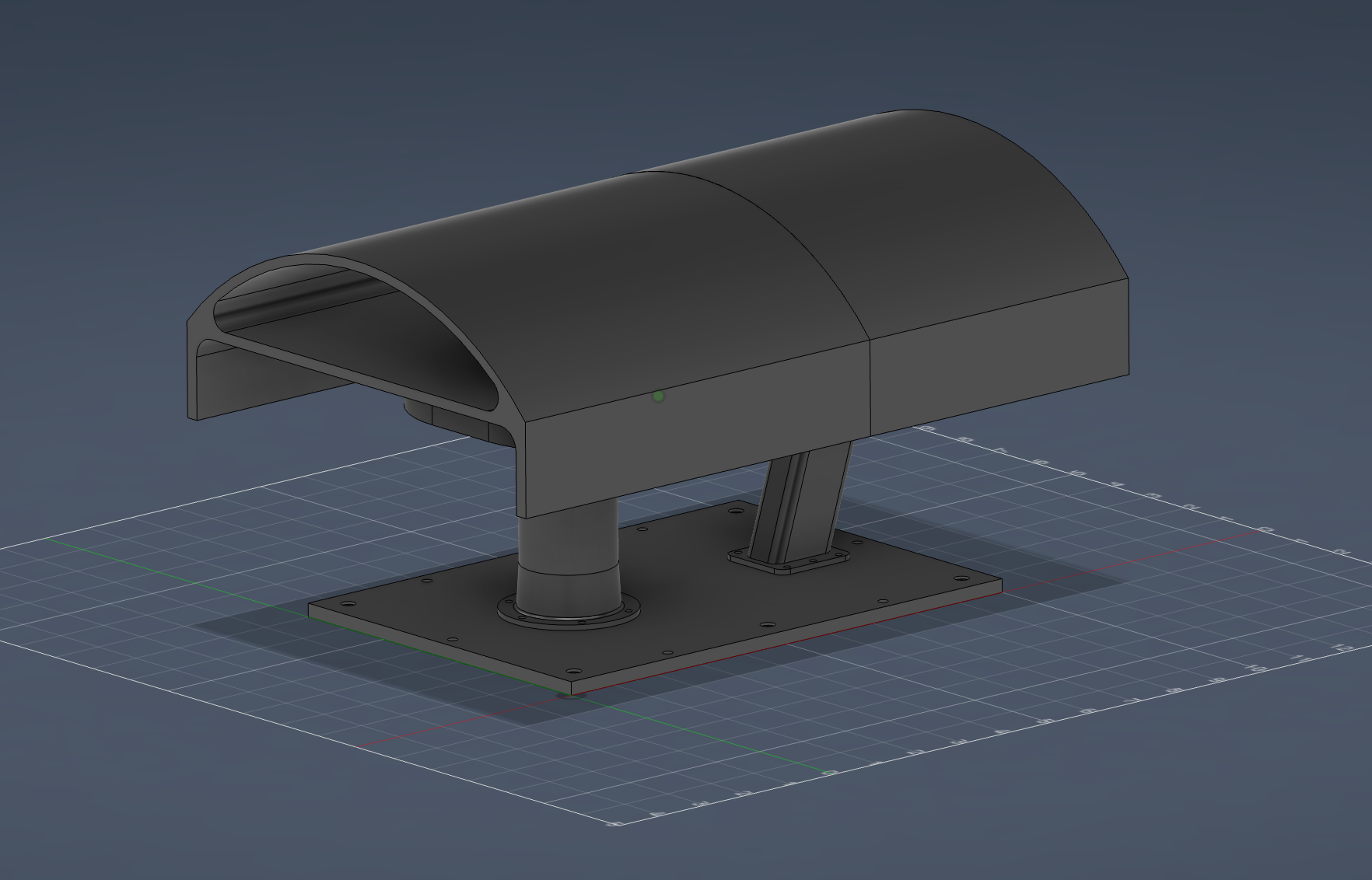
Finally, I started modeling the ceiling and roof elements. The ceiling will give the structure more rigidity while also acting as the housing for the micro controller and relay. The roof structure is split into two components so that it can be printed. It is most for aesthetics but will also assist with some of the weather proofing. I imagine each segment being attached to the ceiling component with magnets to allow for easy electronic access. I also printed a much smaller model of the roof as a proof of concept.
2/14/26
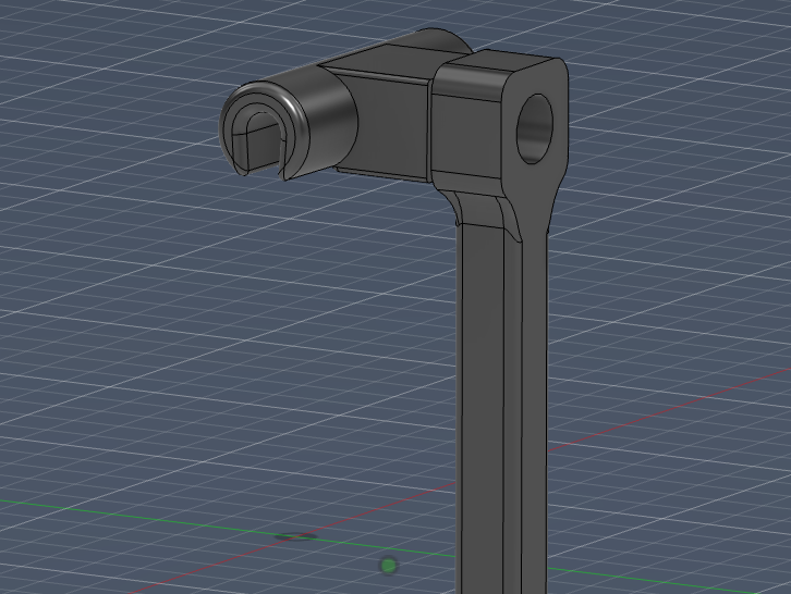
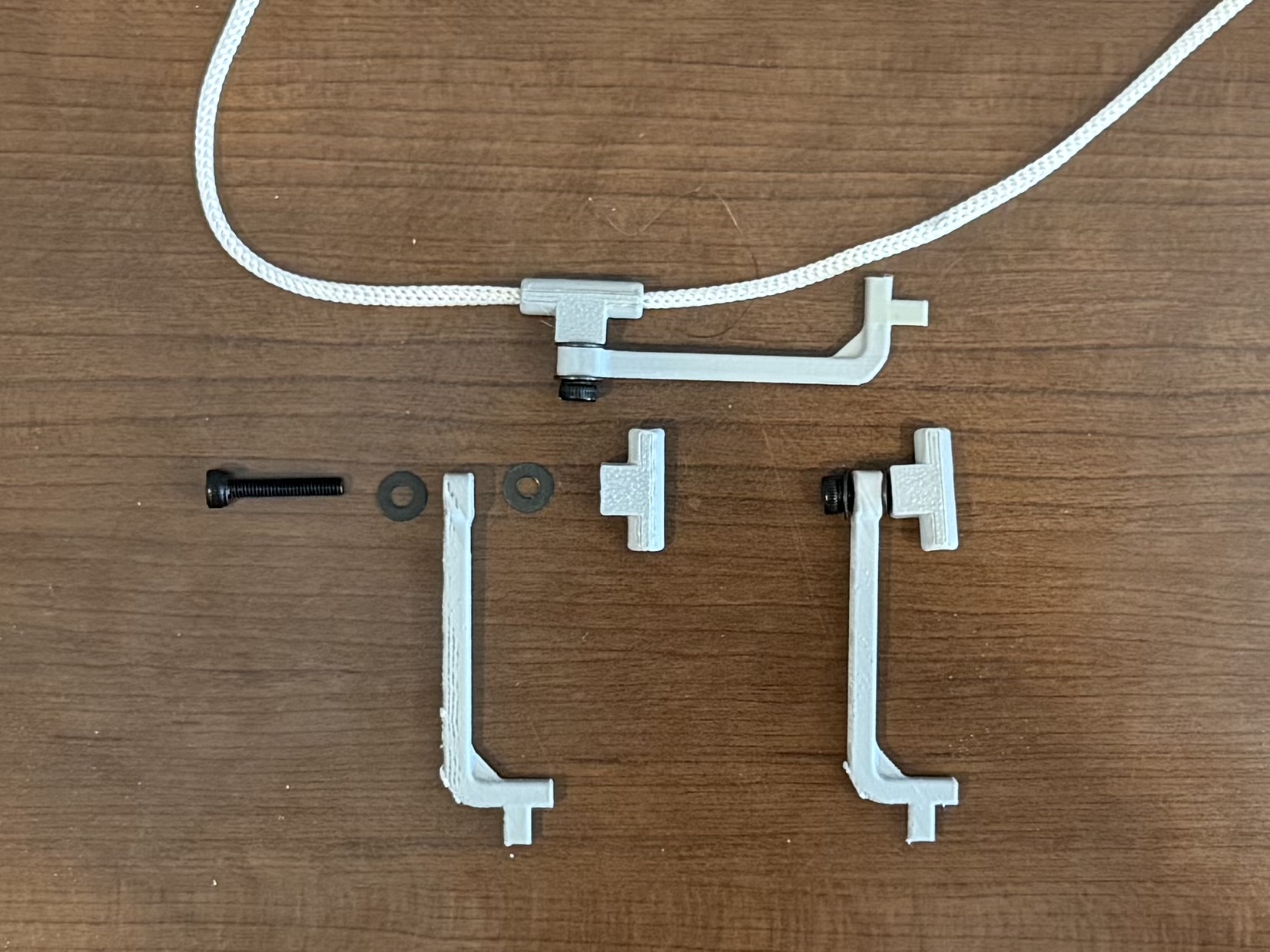
- Updated Cable Grip and Lift Arm
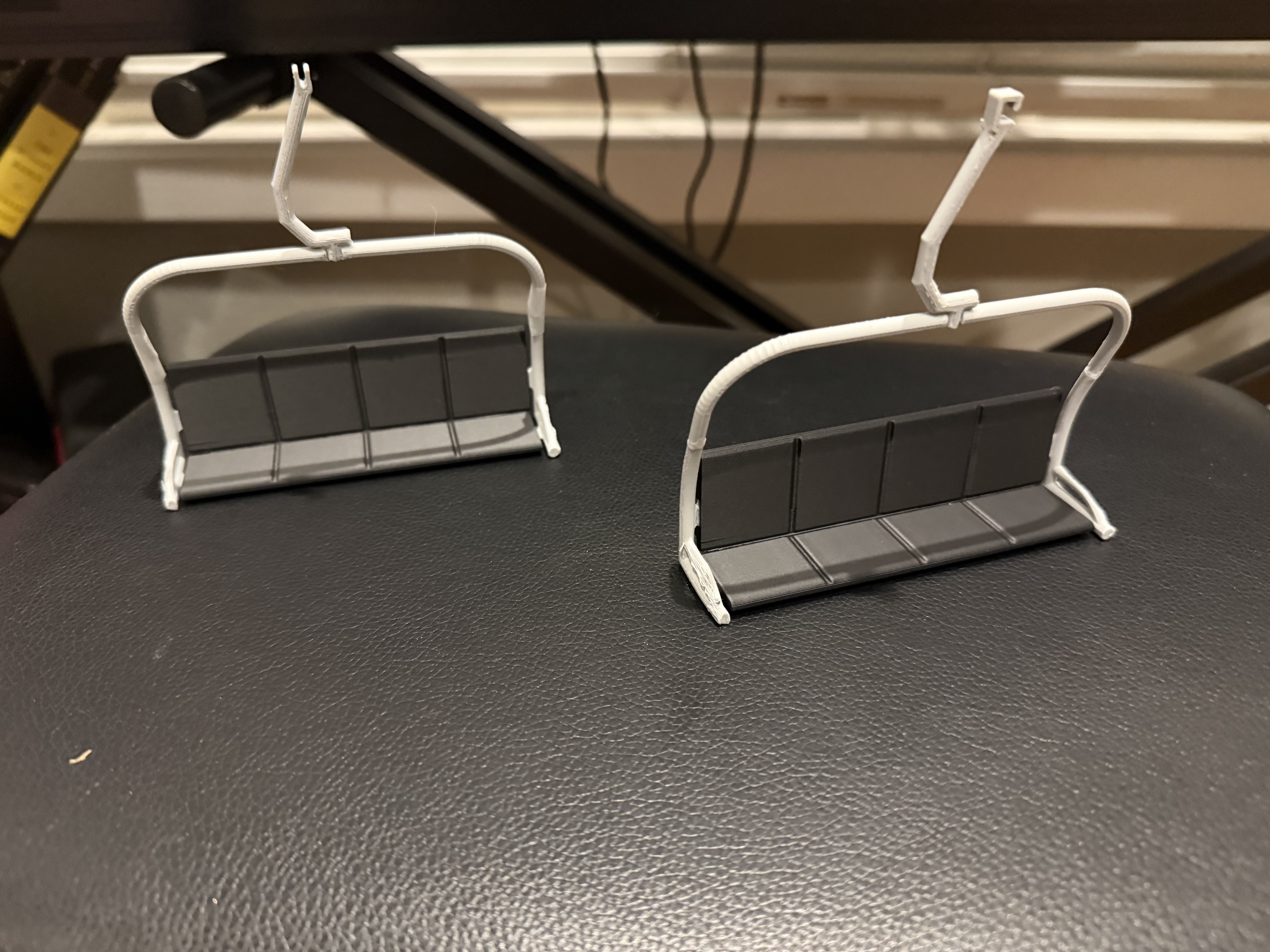
This week I focused on updating the chair designs to make them more robust. The first portion of this work involved redesigning the cable grip to allow for easy attachment and detachment using a M3 screw. I took inspiration from this grip design in a smaller scale model chairlift project. When printing the new cable arms, I played around with the orientation so that the printing layers were out of line with the applied stresses. This will help improve strength while operating. The new grips also allow for the chairs to naturally adjust to hang vertically depending on the angle of the cable. The new designs can be seen below.
2/21/26
- Updated Roof Section CAD
- Updated Ceiling CAD
- Created Base Station Guide Wheel CAD
- Printed First Roof Section, Ceiling, and Bearing Bracket
- Order Additional Components and Tools Needed for Next Steps
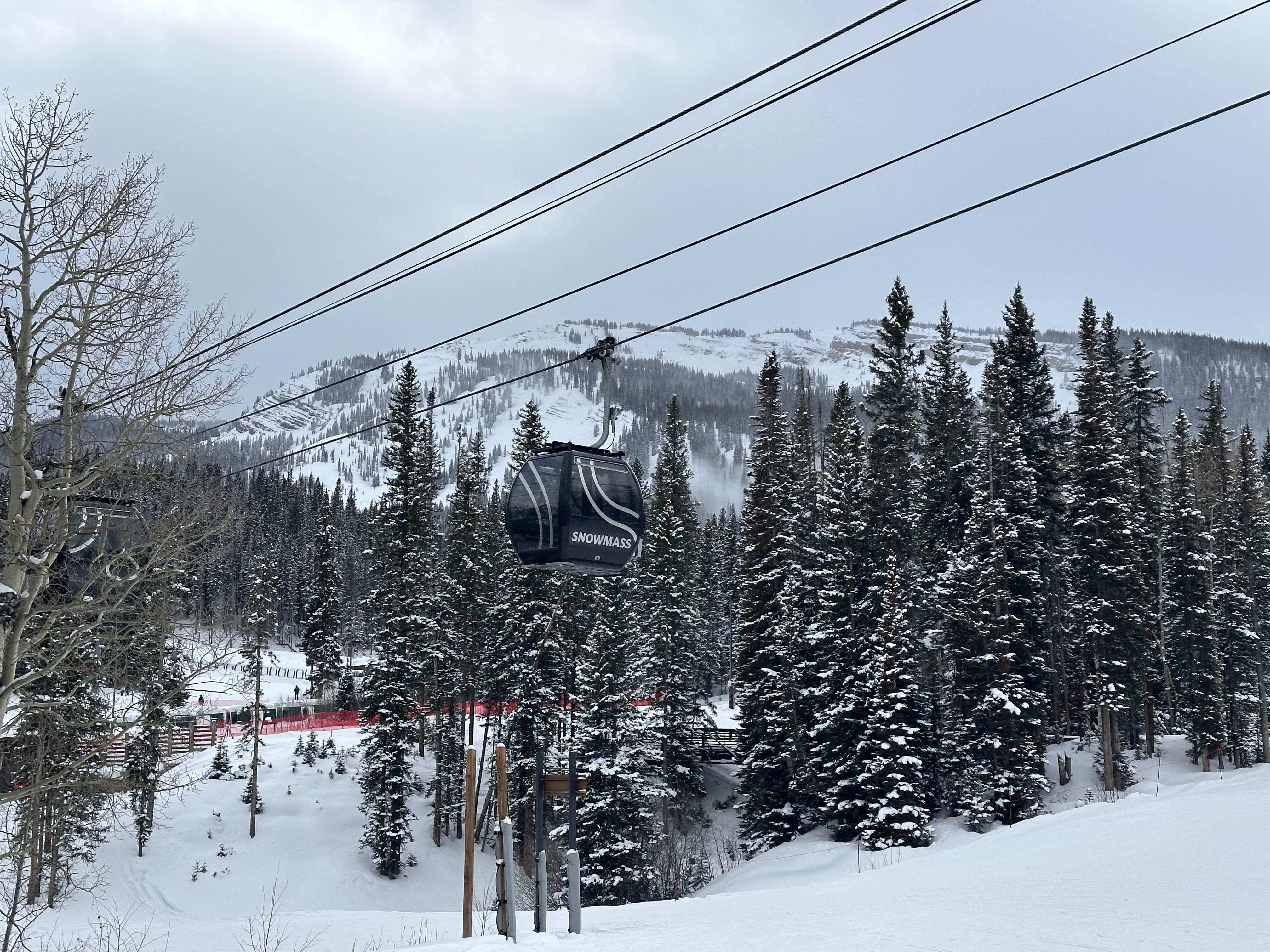
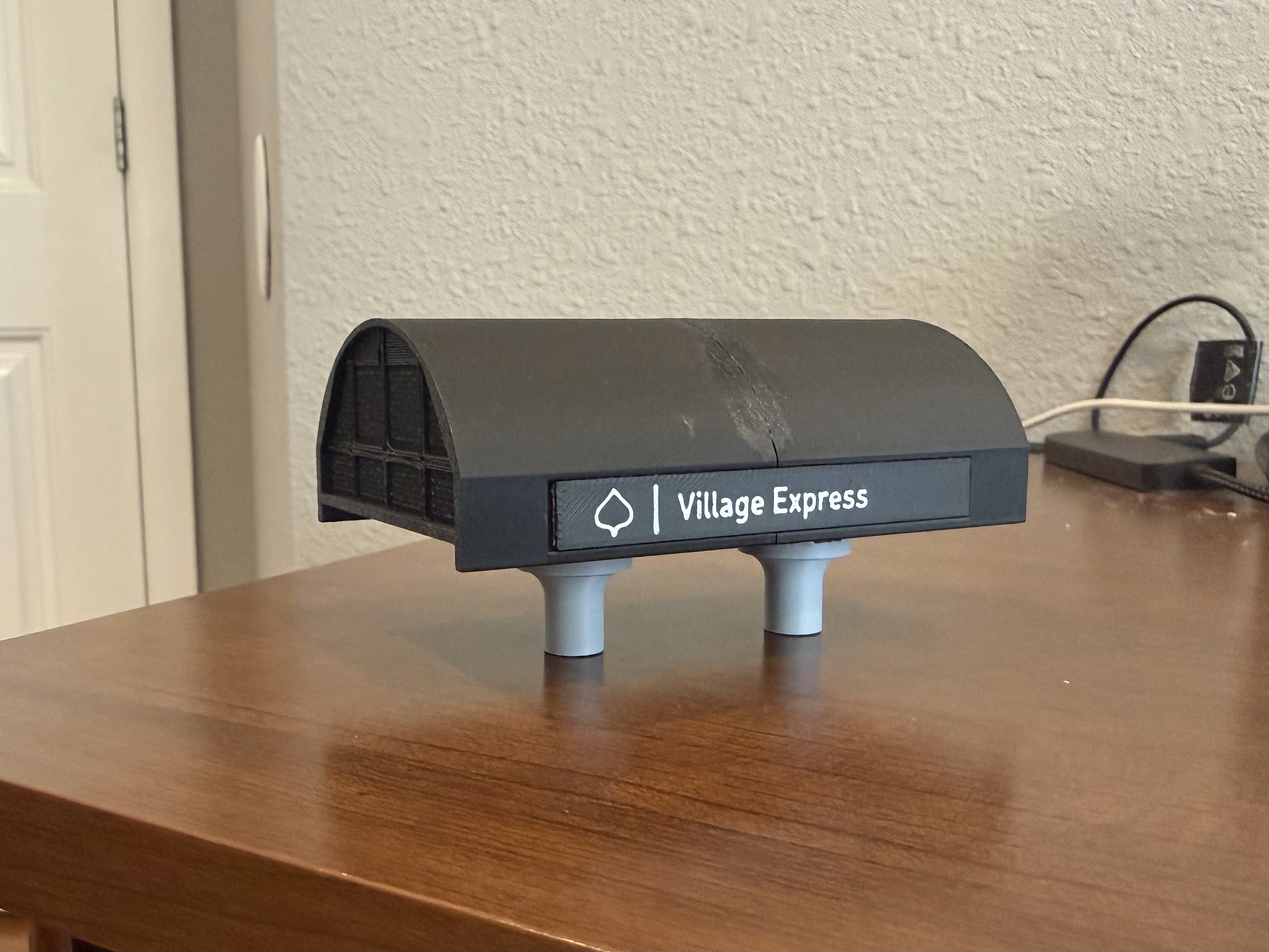
This week I first turned my attention to designing the black roof (inspired by the roof designs of lifts at Snowmass Ski Area) and figuring out how I am going to attach the roof to the ceiling. First, the roof is going to be printed in two sections. This is primarily due to the constraints of the printer I am using, but it also allows easier access to the electronics being stored in the ceiling. My current thought is to use neodymium magnets as attachment points for both roof sections, and I have ordered a set of these. Additionally, the larger roof section poses an issue in that it is effectively cantilevered out over the turn wheel. Right now, my solution to this problem is to introduce a bearing bracket to the top of the turn wheel that slots into the roof segment. This, combined with two magnets located on the supported end of the roof should hopefully be enough to keep the section in place. However, there is a chance that the magnets aren’t strong enough to overcome the torque being applied by gravity, or that the lateral forces adding stress to the bearing cap might be large enough to snap the cap. In this case, I plan on redesigning the roof segment to slide onto two rails that support both roof segments and tie back into the ceiling.
I next turned to printing larger components that have been designed already. Specifically, I printed both ceiling components that bridge from the motor post to the other support post. These can be seen in yellow PLA, as I am running low on the grey PETG, and didn’t want to waste it on a prototype. I also printed the completed cantilevered roof section, as well as the bearing bracket that slots into this roof section.
Finally, I worked on the guide wheels needed on either side of the turn wheel to facilitate smooth transition from the turn wheel to the first towers. This consists of a single wheel directly adjacent to the turn wheel in which the cable runs over, as well as a three-wheel assembly that can pivot which the cable will run under.