RC Flying Wing AE 484: UAV Performance, Design, and Fabrication | Spring 2025
In the Spring 2025 semester, I chose to take the course “UAV Performance, Design, and Fabrication” as one of my technical electives. The goal of this course was to complete a shorter senior capstone type of project in which you worked on a team to design, build, and evaluate an unmanned aerial vehicle (UAV) according to the given year’s design specs. For this semester of the course, we were tasked with making a tailless “flying wing” aircraft that had a mass no greater than 3 lbs. and was capable of carrying a very small payload.
For more details on the design specs, please read the final report that was prepared for the project. This page will primarily focus on areas of the project that are of particular interest to me or aren’t covered in the report.
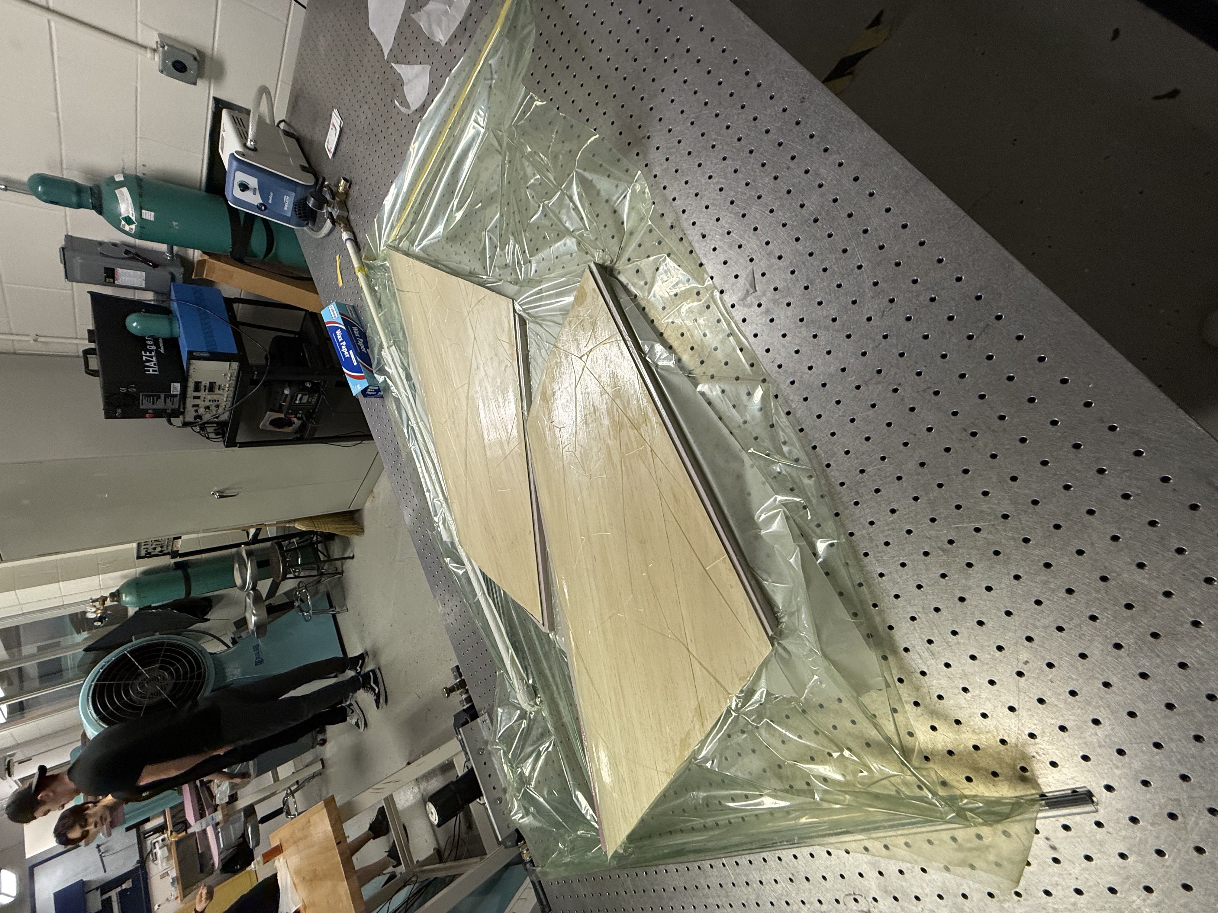
A large focus from my professor, Prof. Gregory Elliott, was the manufacturing aspect of the project. One very interesting hands-on technique that we learned for the project was vacuum bagging. This particular process is used in composites manufacturing and is typically done by placing the two materials you would like to combine into a vacuum sealed bag along with a layer of adhesive in between them. This is commonly seen in the aerospace field with carbon fiber composites manufacturing in which multiple layers of carbon fiber sheet are “laid up” and placed in the vacuum bag. I’ve actually been able to do some hands on prepreg carbon fiber layups during my time as an intern for Aurora Flight Sciences, but that is a bit different than the vacuum bagging done for this project.
In this project, we had foam wing cores manufactured to the precise airfoil geometry that we had chosen (our foam core was actually cut incorrectly, but the plane still flew with some clever weight addition!). Then, we took sheets of balsa wood that were cut to the rough geometry of the wing core’s top and bottom surfaces and glued them to the core. Finally, we placed the balsa/foam wing into a vacuum bag and used the bagging process to fuse the two materials together. The bagged wings can be seen in the image above.
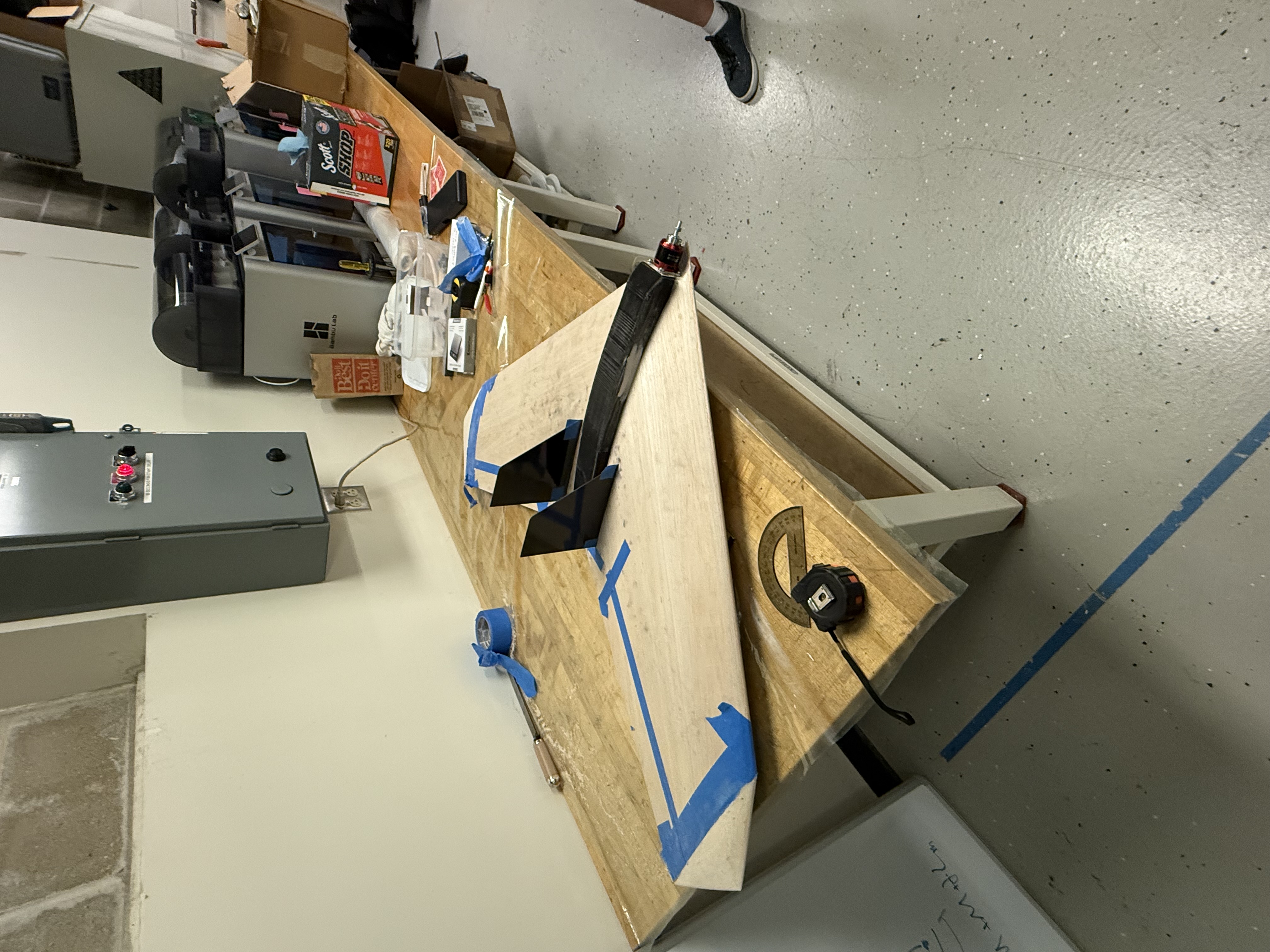
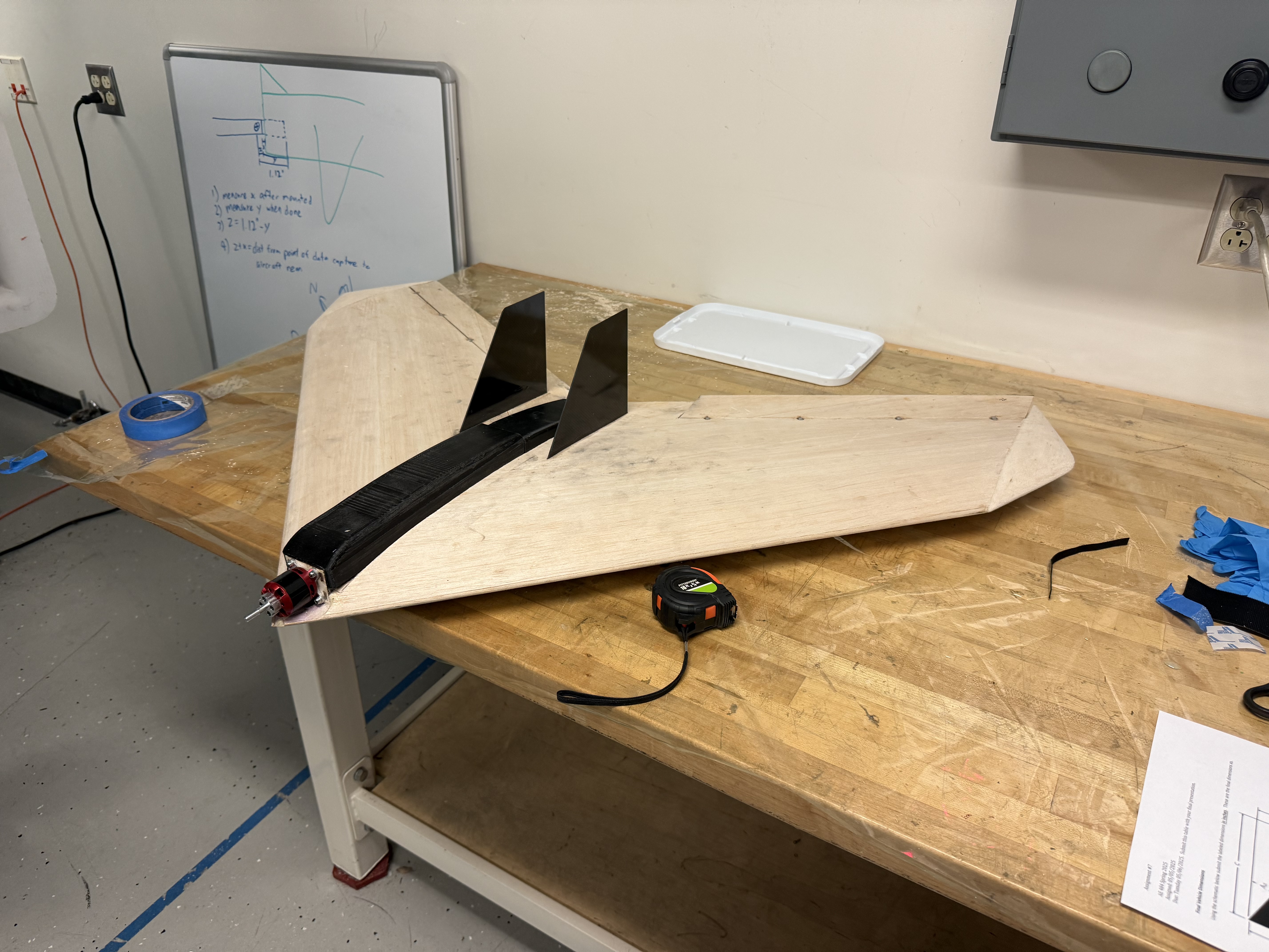
Some other important fabrication techniques that we used for this project were laser cutting and 3D printing. Specifically, we 3D printed our fuselage cap, which is the narrow black segment you can see in the center of the wing. We laser cut the bass wood structural elements that tie the motor back into the wing. These are located underneath the fuselage cover. Additionally, we learned how to use a knee mill during an arranged lab section of the class in which we manufactured a simple aluminum component. We did not end up using this knowledge to manufacture any parts of our aircraft.
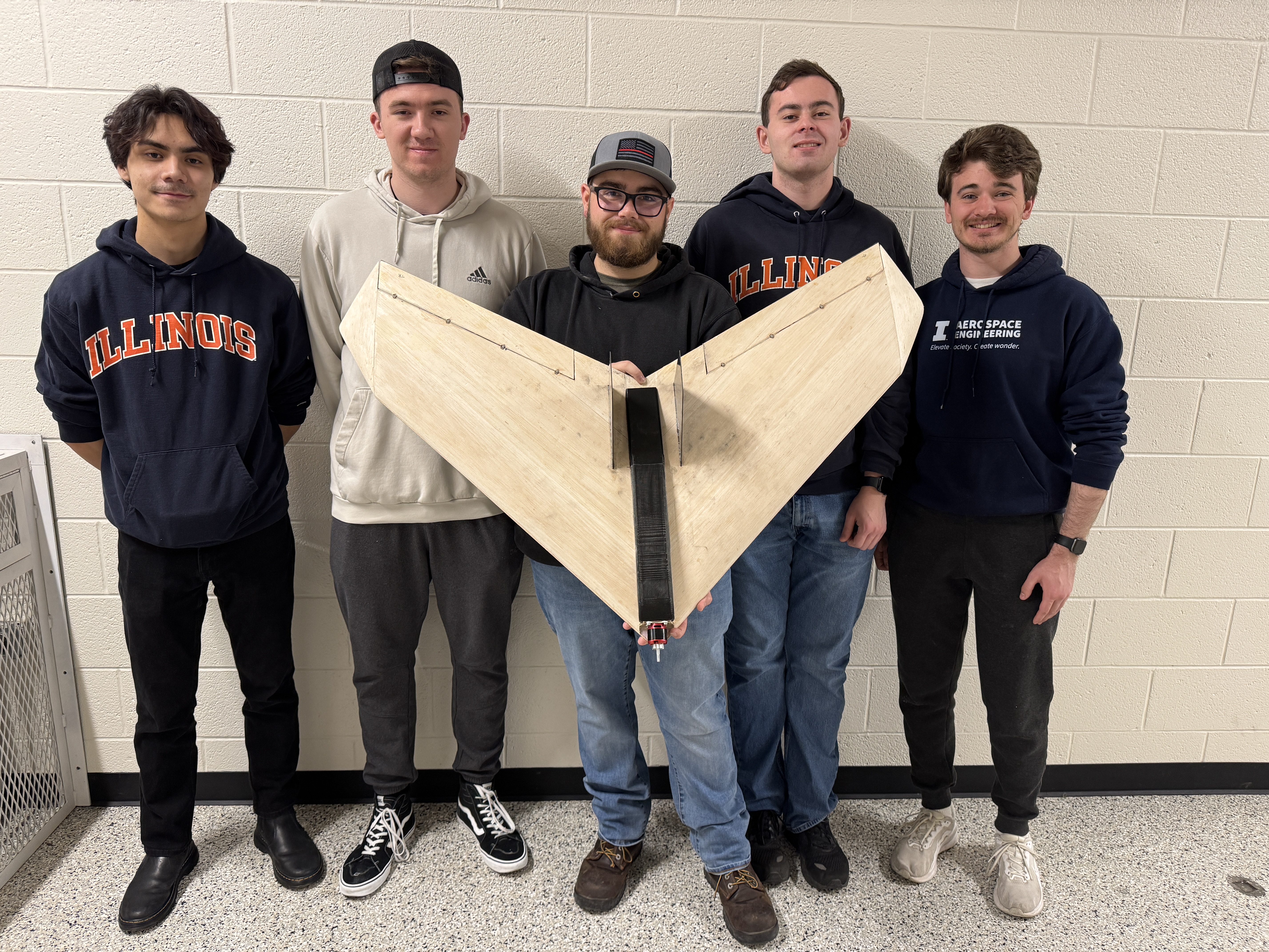
I actually wasn’t able to see the aircraft fly in person. The test date was set after I had already left Champaign for my summer internship in Virginia. Luckily, my teammates were able to take a video of the flight test (a short clip of which is at the top of this page), and it was a resounding success! In fact, we were the only team of 3 that had a successful flight on the first attempt. A big shoutout to my team members; Justin Abel, Tyler Gralewski, Patrick Swiatek, and Jaden Tran for their work on the project as well.
I specifically did the design work for the motor bulkhead and frame, with my team members altering it slightly to better fit the later designed fuselage cap. I also modeled all preexisting components in CAD to help with visualizing our design work, and I created dimensioned engineering drawings for every individual component. I also completed the calculated performance analysis in the paper, and I was a part of the group discussions on all major design choices, such as airfoil profile and overall layout.